Designing a New Build Plate
Tags: design and innovatePersonhours: 6
Task: Model and CNC a new build plate for TomBot
The renowned architect Frank Lloyd Wright once said, “The longer I live, the more beautiful life becomes.” This, however, is not the case for our build plate. Throughout the course of the season the plate has seen extensive use and has endured much abuse, which can be seen in the large cracks forming on the plate. Although there are many temporary remedies, such as attaching plates to hold it together. These are not permanent solutions and not only appear bad, but can only temporarily reduce the problem, as more cracks will inevitably form.
The first build plate was cut from Polycarb on a bandsaw from a pattern. This process resulted in many imperfections and uneven cutting, subtracting from the sleek circular design. This second time around we’re going to completely CNC the whole plate, including the wholes for bolts and wires. Using a CNC ensures a greater precision and guarantees a higher quality build plate.
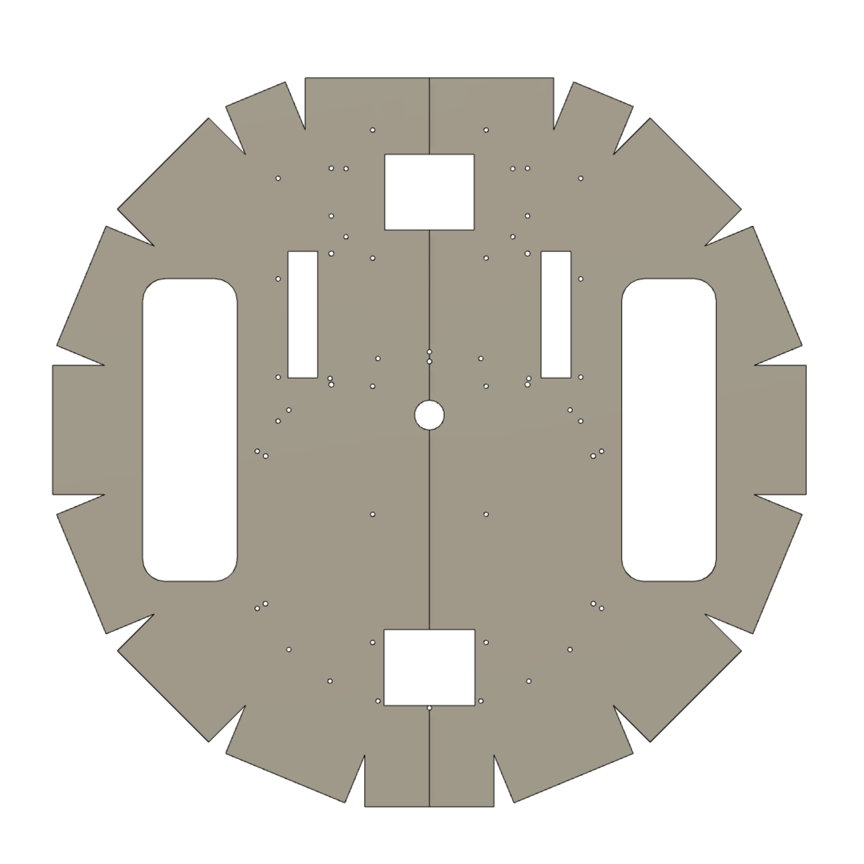
Cracks weren’t the only problems facing the first build plate. Drive testing revealed a major flaw with the design, the flaps that folded down from the plate were too short, causing the foundation to get stuck under the robot during matches. This is obviously undesirable as no one likes a robot who drags a giant plastic plate around the whole match. To fix this we just slightly extended those flaps on the model to extend past the height of the foundation. There was also another issue, the bolts that secured the omni-wheels to the build plate were difficult to access because they were to close to one of the Rev rails. To fix this we just slightly increased that distance but also had to ensure that there was enough length on the ends of the axle to comfortably secure the wheel mounts. Other, smaller, issues such as wiring holes were also solved by providing adequate space for wiring next to the expansion hub mount.
Above you can see an image of the completed build plate. To ensure accuracy one side was developed them mirrored. This removes any variability within the model and creates a symmetric object. The screw holes were created by imposing the turret mounts and rev rails from the previous robot model onto the current one, providing an accurate placement for each hole.
Next Steps:
After completing the model, we will print the pattern on a large sheet of paper and verify the placement of all the components that are to be attached. If there are any inaccuracies they will be fixed. We then have to develop a CAM path for the CNC machine. Construction of the second robot will begin once the second plate is completed.